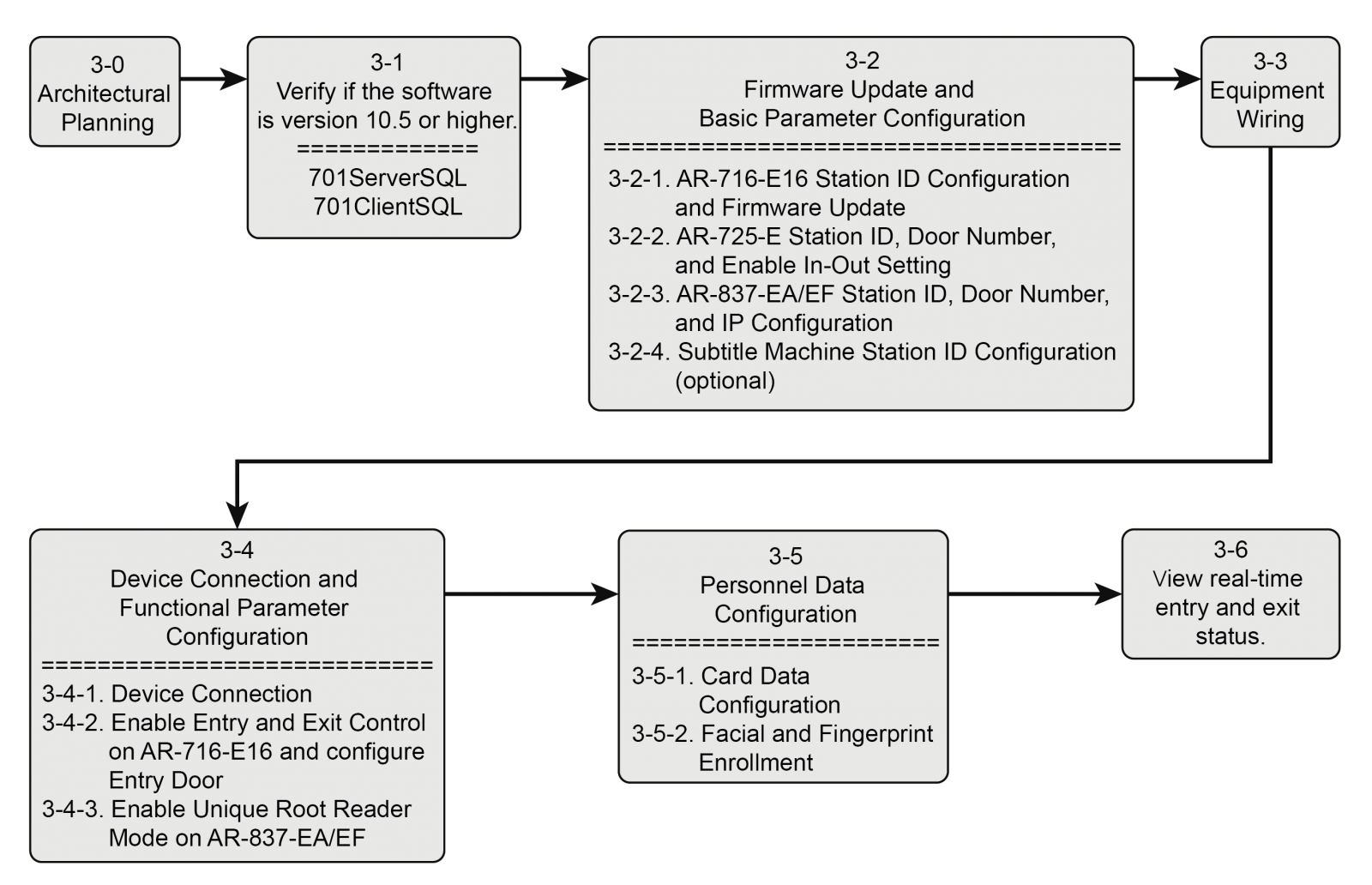
Table of Contents (Click to Jump to Content)
1.Application Function Description
2.Introduction to Two Architectures of the Multi-Entrance and Multi-Exit Facial Recognition System
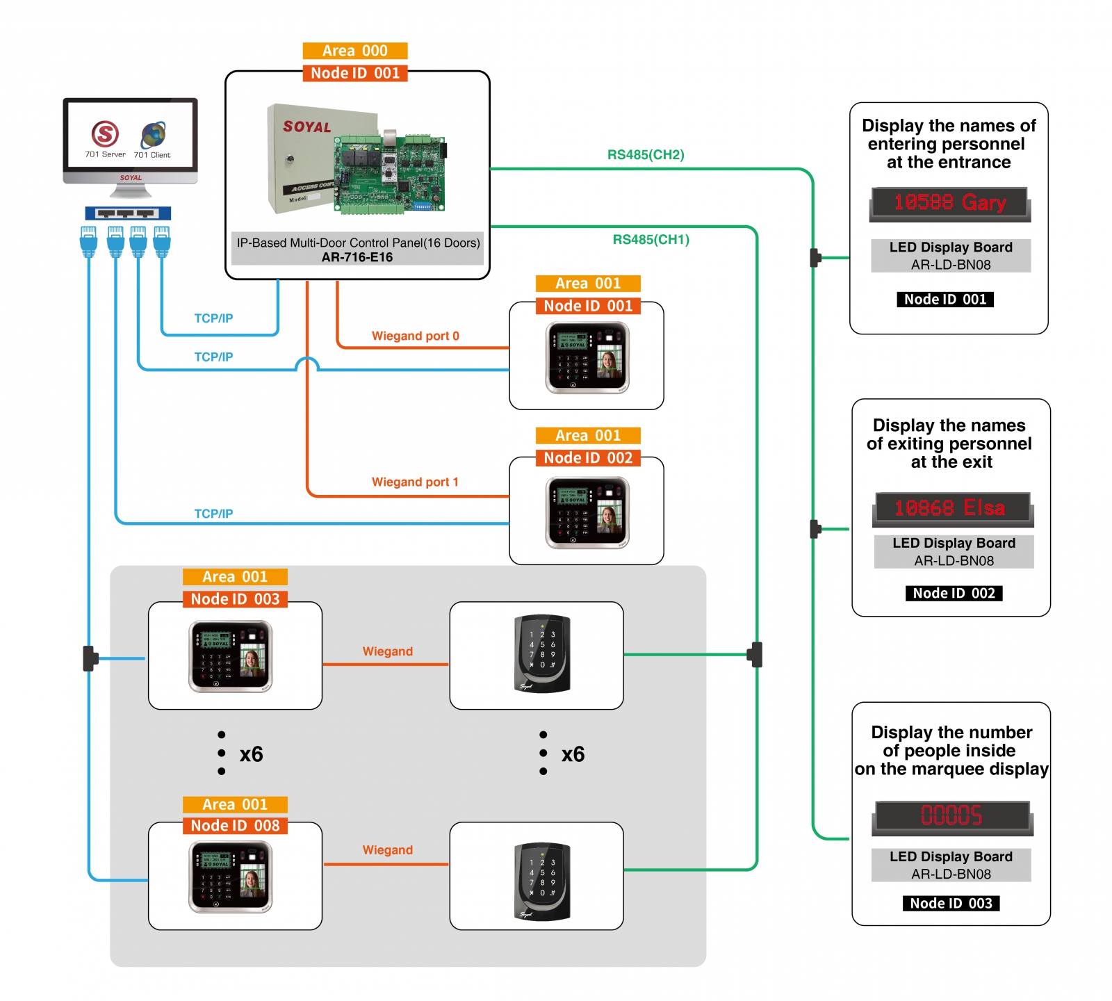
2-1 Example of Architecture Diagram for Method One
3-1. Confirming Software Version 10v5 or later
3-2. Firmware Update and Basic Parameter Configuration
3-2-1. AR-716-E16 Station Number Setting and Firmware Update
3-2-2. AR-725-E Station Number, Phone Number, and Enable One In One Out Setting
3-2-3. AR-837-EA/EF Station Number, Phone Number, and IP Configuration
3-2-4. Subtitle Machine Station Number Setting (Optional)
3-4. Equipment Connection and Function Parameter Configuration
3-4-2. Enable In and Out Control on AR-716-E16 and Set Entry Gate
3-4-3. Enable Unique Root Reader Mode on AR-837-EA/EF
3-5. Personnel Data Configuration
3-5-1. Card Data Configuration
3-5-2. Register Face and Fingerprint Data
3-6. View Real-time Entry and Exit Status
Q1. When clicking on the entry and exit status, "The Controller didn't support this function!" message is displayed.
Q2. One of the card readers is unable to display one in one out correctly.
1-Application Function Description
Access control is required for personnel entering and exiting designated areas. Administrators can remotely view real-time personnel data within the area and calculate the total number of people via 701ClientSQL. This effectively enhances the safety management of personnel within the area.
- Remote counting of personnel who have not left the designated area within the specified time, including generating a list of names and quantities, and exporting record files to enhance personnel safety management.
- Installation of subtitle machines at entrances and exits as required to display the user's address and name of entering and exiting personnel in real-time.
- Installation of subtitle machines as required to display the total number of personnel within the area.
- Equipped with a reset button for the person count, allowing management personnel to reset the count easily for each session of personnel counting.
- The on-site access control follows the one-in-one-out control policy, effectively preventing unauthorized entry into the controlled area.
(This means that access is only granted if the sequence of entry and exit follows the "in → out → in → out" principle.) - Facial and fingerprint data can be collected by one of the on-site controllers and remotely read and written to multiple controllers via TCP/IP communication by the software. There is no need to register repeatedly on each controller on-site.
- Customizable time periods for checking and resetting the person count, automatically checking the number of people within the area, and triggering alarms automatically (optional).
2- Introduction to Two Architectures of the Multi-Entrance and Multi-Exit Facial Recognition System
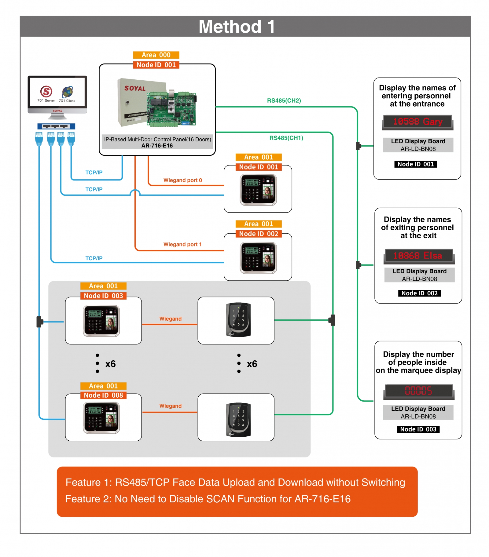
2-1 Example of Architecture Diagram for Method One
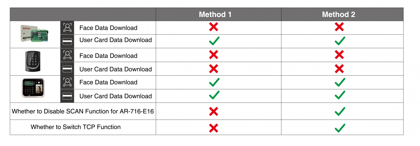
2-2 Equipment List:
* Listed as special function software/firmware, please make sure to update to achieve the functionality of this use case. ▶SOYAL Official Resource Download Zone
| Classification | Product | Product Name | Software/Firmware Version | Feature | Quantity |
| Software | Access Control and IO Monitoring Server Software | 10v5 2023-05-31 or later versions | 1.Device connection status monitoring 2.Personnel data parameter configuration | 1 | |
| Access Control and Graphic Animation Software | 10v5 2023-05-25 or later versions | 1.Personnel data editing 2.View real-time on-site personnel data and quantity 3.Complete event log | 1 Both can be installed simultaneously, but please do not activate them at the same time. | ||
| * Portable 701Client 701Client10v5 230526 portable SHOW_INSIDE_NUM顯示場內人數.exe or later versions (▶701ClientSQL Standard version & Portable version differences) | 1. Display total number of on-site personnel 2. Personnel data editing 3. View real-time on-site personnel data and quantity 4. Complete event log | ||||
| Hardware |
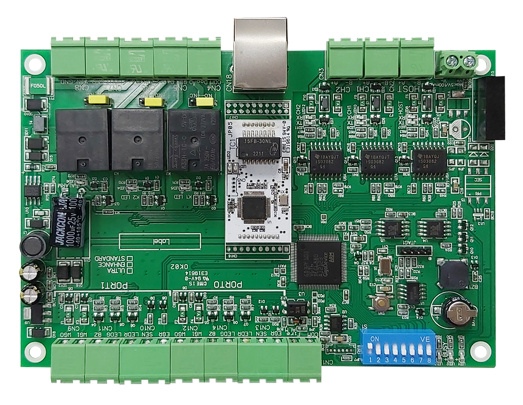
| IP-Based Multi-Door Control Panel (16 Doors) | *APS721Ev2__V0405_230526 人流字幕機顯示 站號1~4進 5~8出.STM or later versions | 1. Unified management of parameter settings for multiple card readers 2. Determine whether the personnel identification matches the access permission. | 1 |
|
| Illuminated Touch Keypad Multi-Function Controller | APS725Ev2__V0405_230413.STM or later versions | 1. Read the personnel identification data of people entering and exiting the premises and return it to multiple door controllers to determine access permission | <6 | |
.png) AR-837-EA AR-837-EA | Graphic Display Multi-Function Proximity Controller | APS837EF___V0405 230602 106F.STM or later versions | 1 | ||
 AR-837-EF AR-837-EF | RFID LCD Fingerprint Access Controller | APS837EF___V0405_230602.STM or later versions | 1 | ||
| Touchless Infrared Sensor Push Button(Anti-Interference) | N/A | 1. Reset the entry/exit status of all personnel, reset the people amount to zero directly. | 1 | ||
| Purchasing equipment |  AR-LD-BN08 AR-LD-BN08 | LED Display Board | N/A | 1. Display user addresses and names of entering/exiting personnel 2. Display total number of on-site personnel | 3 |
|
| Serial-to-Ethernet Server&Modbus RTU Over TCP | APX727i3___V0503 220804.STM or later versions | Choose the communication method between AR-716-E16 and the software based on your needs: 1. Direct TCP/IP communication (without using a converter) 2. TCP to RS485 communication 3. USB to RS485 communication | 1 | |
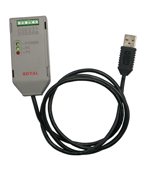 AR-321-CM AR-321-CM | Isolated USB to RS485 Converter | ▶Comparison Chart of Driver Versions of AR-321CM Chip and Operation System | 1 |
.png)
Before starting the operation, it is strongly recommended to draw a planning architecture diagram based on the site requirements. The main purposes are as follows:
- Avoiding IP or station number duplication:
Inventory the available station numbers and IP locations on site in advance and allocate them to the equipment. This helps to avoid errors caused by duplicate configurations and saves additional troubleshooting time. - Enhancing troubleshooting speed:
Site personnel can quickly understand the site status based on the architecture diagram and systematically troubleshoot anomalies, thereby accelerating the troubleshooting process. - Easy expansion and maintenance of the architecture:
Whether it is regular equipment maintenance or equipment expansion after scaling, the system status can be quickly checked and evaluated based on the architecture diagram.
The diagram below illustrates the architecture used in this example:
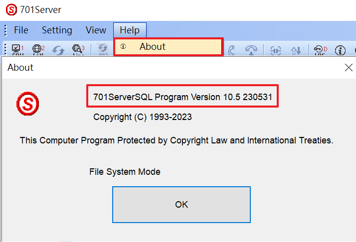
3-1. Confirming Software Version 10v5 or later
Please confirm whether the software versions for 701ServerSQL and 701ClientSQL are 10v5 or later. After opening the software, click on the "About" option in the help menu to display the current version of the software.
.png)
*Note: Before upgrading to 701ServerSQL and 701ClientSQL, please back up your existing data. For detailed instructions, please refer to the ▶701ServerSQL & 701ClientSQL Installation Guide
3-2.Firmware Update and Basic Parameter Configuration
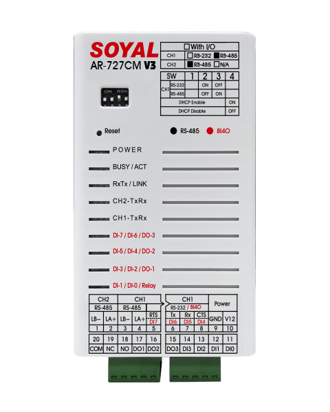
3-2-1. AR-716-E16 Station Number Setting and Firmware Update
Step 1: Setting the Station Number
How to set the station number for AR-716-E16 using the dip switches?
Station Number = Sum of the setting values where the dip switches are ON.
Below the dip switches, there are numbers 1 to 8, representing the respective setting values (see the table below). When the dip switch is ON, it means that its designated value should be included in the calculation.
For example, if the station number is 30, it is equal to the sum of setting values 2, 4, 8, and 16. Therefore, dip switch numbers 2, 3, 4, and 5 should be ON, while the rest should be OFF.
.png)
Step 2: Updating the Firmware
Firmware Name: APS721Ev2__V0405_230526 人流字幕機顯示 站號1~4進5~8出.STM (或之後版本)
For detailed firmware update instructions, please refer to the following: ▶UDP UPDATER Manual
3-2-2. AR-725-E Station Number, Phone Number, and Enable One In One Out Setting
Step 1: Set the station number and gate number. For detailed instructions, please refer to the ▶AR-725-E Manual (P.5 Station Number Change Command)
Step 2: Enable the "one in, one out" function and specify it as either an entrance gate or an exit gate. For detailed instructions, please refer to the ▶AR-725-E Manual (P.6 One In, One Out Control Button Command)
3-2-3. AR-837-EA/EF Station Number, Phone Number, and IP Configuration
Both of these devices are screen display controllers, and you can directly set them up through the menu list in editing mode.
For detailed configuration instructions, please refer to the ▶AR-837-EA Manual and ▶AR-837-EF Manual complete menu of available commands for all functions.
3-2-4. Subtitle Machine Station Number Setting (Optional)
Step 1: Set the station number of the "Visitor In" display subtitle machine to 001.
Step 2: Set the station number of the "Visitor Out" display subtitle machine to 002.
Step 3: Set the station number of the "Total Visitors Inside" display subtitle machine to 003.
Connect the devices according to the planned architecture.
*All card machines (including AR-837-EA/EF) should be connected to AR-716-E16 with a common ground connection. For a complete description of the connection points, please refer to the▶AR-716-E16 Manual
.png)
âNote 1: The biometric-based controller under this architecture must be connected to two types of communication simultaneously:
(1) TCP/IP communication of the controller itself:
Remote reading and writing of facial and fingerprint recognition data, eliminating the need for repeated registration on individual controllers.
(2) Wiegand Port of AR-716-E16:
Unified management of access control for personnel by AR-716-E16.
âNote 2: When Fire-ALM contacts are connected in common ground, the access status of all personnel can be reset.
âNote 3: The station numbers for Wiegand Port are fixed as 1 and 2. When Wiegand Port and RS485 are both connected to the card reader, the station numbers for RS485 card readers start from 003.
3-4. Equipment Connection and Function Parameter Configuration
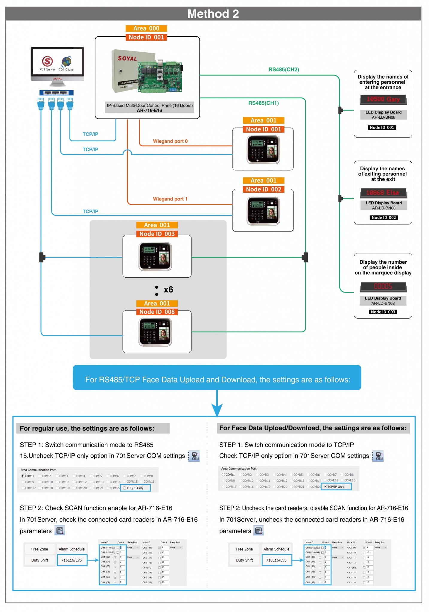
Step 1: Open 701ServerSQL and click on "COM" to select the area and connection method.
*Step 1: Open 701ServerSQL and click on "COM" to select the area and connection method.
.png)
Step 2: Open the [LAN] page, check the device station number, and fill in the controller's IP address and controller name sequentially.
.png)
Step 3: Click on the [Line] page to confirm if the device is correctly connected
.png)
Further reading: Why is the controller connection status not displayed on the Line page in multi-door controllers?
RS485 CH1: You need to check the station number in the parameter setting page of AR-716-E16, save it, and write it to the card reader.
Wiegand Port: The card readers under Wiegand Port do not display the connection status, so there is no need to check the station number.
Note: The sub-nodes (station numbers) for Wiegand Port are fixed as 1 and 2. When both Wiegand Port and RS485 are connected to the card reader, the sub-nodes for RS485 start from 003.
.png)
3-4-2. Enable In and Out Control on AR-716-E16 and Set Entry Gate
Step 1. Open the "[H/E-series Controller Parameter Edit]" page.
Step 2. Select the region and station number for the multi-door controller AR-716-E16.
Step 3. Click on "[Read from Controller]".
Step 4. Enable the "Enable Antipassback" feature.
þMain = Enable this feature on AR-716-E16.
þWGA = Enable this feature on the card reader of the Wiegand Port under AR-716-E16.
Step 5. Set Is entry door.
þMain= The card reader of Wiegand Port 0 is set as the entrance door.
þWGA = The card reader of Wiegand Port 1 is set as the entrance door.
Step 6. After completing the settings, click "Save" and Write to controller.
(2).png)
3-4-3. Enable Unique Root Reader Mode on AR-837-EA/EF
Step 1. Open the "[H/E-series Controller Parameter Edit]" within 701ServerSQL.
Step 2. Select the region and station number for the controller.
Step 3. Click on "[Read from Controller]" to read the device parameter settings.
Step 4. Check the "[Ev5 WG out/Hv3 Lift out]" option to enable the unique root reader mode.
Step 5. Click on "[Write to Controller]" to write the data.
-1.png)
Further Reading: How to determine if the screen controller is enabled for unique root reader mode?
To determine this from the main display in standby mode, please refer to the table below:
| 唯根讀頭模式
| 控制器模式
|
3-5. Personnel Data Configuration
3-5-1. Card Data Configuration
Step 1. Open 701ClientSQL and click on the card data editing page.
Step 2. Select the user location and set up the user data sequentially.
*Note: To include personnel under retention management, enable the one in and one out function.
Further Reading: ▶How to use “import/export to text file” function to edit card efficiently through text file or excel?
Step 3. After completing the settings, save the file and close this page.
.png)
Step 4. Open the download settings page.
Step 5. Check the station numbers for AR-716-E16 (multi-door controller) and AR-837-EA/EF (face/fingerprint recognition controller).
Step 6. After selecting the user location range, click on card download to download the card data to the controller.
(1).png)
3-5-2. Register Face and Fingerprint Data
Enter the controller editing mode à Menu 2: User data à Menu 6: Register face features/Register fingerprint à Follow the on-screen prompts to register face or fingerprint.
Further Reading: ▶How to transfer/download/write fingerprint data to the others AR-837EF?
3-6. View Real-time Entry and Exit Status
Step 1. Open 701ClientSQL to view the complete event log.
.png)
Step 2. Open the "Access Status" page.
Step 3. Select the controller station number for AR-716-E16, then click on "Read" to display the list of personnel inside the facility.
Step 4. Check the status of user locations, which are: R for entry, £ for exit, © for initial state (no record of entry or exit).
Step 5. View the list of personnel inside the facility.
Step 6. View the total number of personnel inside the facility.
* Requires the use of the portable version software 701Client10v5 230526 portable SHOW_INSIDE_NUM顯示場內人數.exeor later versions to support this feature. (▶How to install the portable version of 701ClientSQL?)
.png)
Further reading: How to reset the entry/exit status for all personnel?
To reset the entry/exit status for all personnel, trigger the fire input of CN15 inside AR-716-E16. This will reset all personnel to the initial state.
Please refer to the complete contact description at▶AR-716-E16 Manual
Q1. When clicking on the entry and exit status, "The Controller didn't support this function!" message is displayed.
.png)
àPIease confirm if AR-716-E16 has been updated to the retention version firmware.
Q2. One of the card readers is unable to display one in one out correctly.
àPlease confirm if the wiring is correct (all devices in this architecture should be connected to a common ground).